5.2.1.1 Gap Requirements for Bonded Assemblies
Gap Effect in Rigid Adhesives
As a general rule, high modulus adhesives (rigid adhesives) possess high tensile strengths. Additionally, there is an inverse relationship between the bond line thickness and the tensile strength of adhesives. This is not an absolute rule; however, some adhesives require a specific gap to achieve maximum strength. Where this induced gap is critical; the adhesive will have spacer beads within the formulation and the gap will be specifically addressed in the (TDS) of the corresponding adhesive. This is most important during clamping operations as an induced gap relates to the overall clamp force applied to the assembly; care should be taken not to apply too much force, as this may cause the spacers to be crushed or displaced and the induced gap will be less than specified, resulting in a lower strength bond than desired.
If an induced gap is not specifically advised, using rigid adhesives with thin gaps is usually recommended as long as the bond-line gap is fully filled. Thicker gaps normally result in lower assembly strength because cleavage forces more readily occur due to nonaxial loading or internal stresses in the adhesive.
The most important aspects of the adhesive gap or bond-line thickness for rigid adhesives are magnitude and uniformity, or homogeneity. Generally, it is important to have as thin an adhesive layer as possible without any chance of insufficient coverage. When using rigid adhesives, bond line thicknesses or gaps from 0.02 mm (0.001 in) to 0.20 mm (0.008 in) are recommended, as data show that adhesive strengths do not vary significantly in this range. The optimal bond line thickness is about 0.1 mm (0.004 in), though with thicker adhesive bond lines, there is a higher risk of incorporating voids into the joint. Stresses at the corner of the adhesive/substrate tend to be larger in large gaps, as it is difficult to keep the axial loads aligned (see Joggle Lap Joint, Section 5.1.3) with a very thick bond line.
High modulus, or rigid, adhesives are generally formulated to cure in thin sections. Thicker sections may alter the curing properties, prevent the adhesive from fully curing and result in increased internal stresses due to shrinkage or exotherm during the cure.
The gap should be as uniform as possible, which equates to the substrates being as parallel as possible; by maintaining uniformity in adhesive thickness across the bonded area, strength and stress distribution will be maximised. If the adhesive gap is not uniform, the axial loading will not remain aligned, subsequently translating into cleavage stress on the adhesive.
Several methods may be employed to ensure consistent and correct gaps in the adhesive joint. These include the following:
- Application of pre-calculated pressure (clamp load) during cure.
- Use of fixturing that is specifically designed for the application.
- Application of a shim or insert within the bond line so that a uniform, predetermined thickness can be maintained.
- Use of an adhesive that has spacer beads incorporated into the formulation.
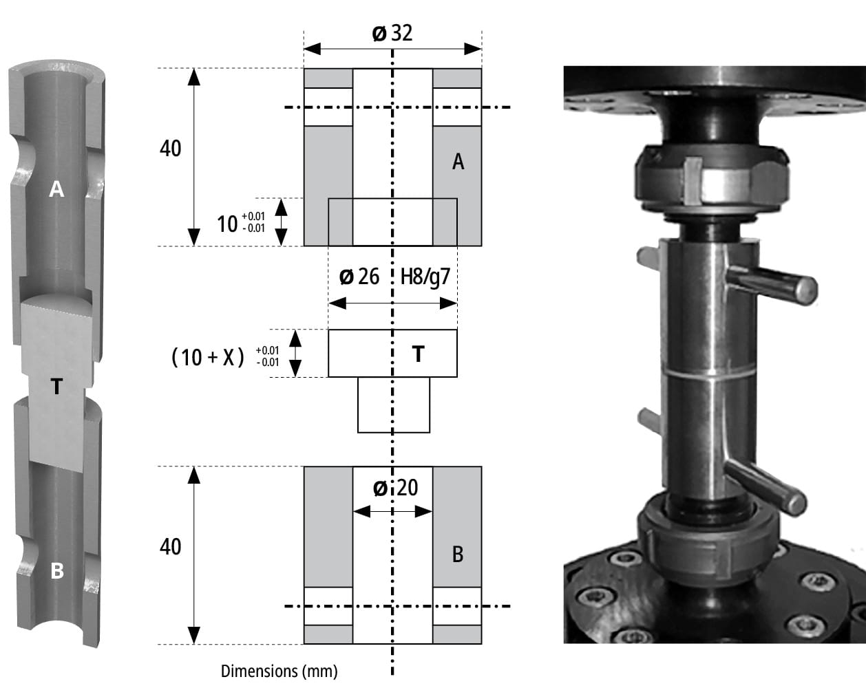
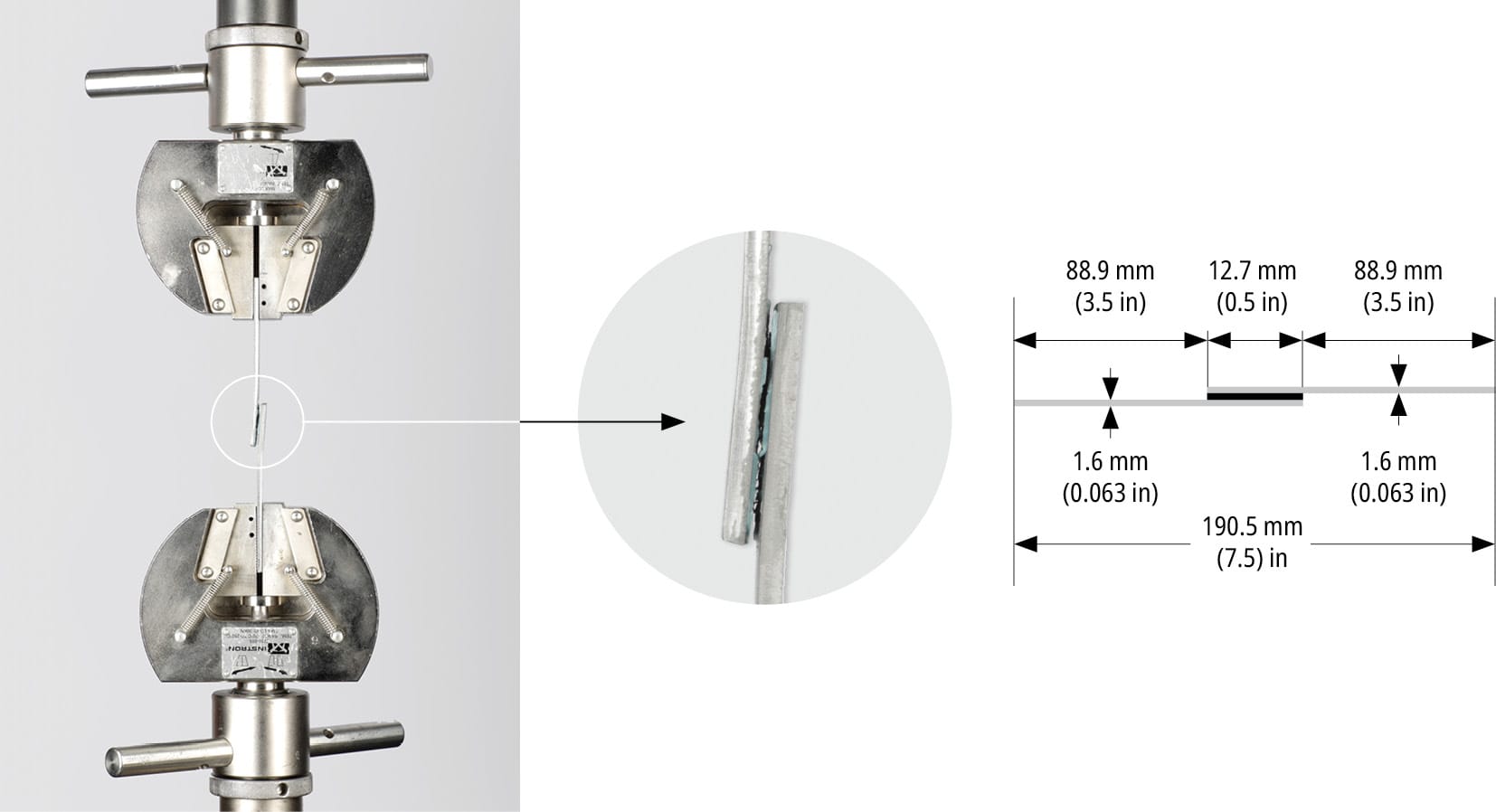
A comparative test was carried out between a two-step, no-mix acrylic adhesive and a 1C epoxy adhesive to evaluate the strengths obtained after curing at various adhesive gaps. The tests were performed using a non-standard joint designed for torque measurements (Figure 124) and according to ASTM D1002-01 to measure tensile shear values (Figure 125). The results of the torque test component are summarised in Table 18.

| Bond Line Thickness (mm) | 0.05 | 0.1 | 0.2 | 0.4 | |
| 2-step acrylic adhesive | Peak torque (Nm) | 73 | 62 | 43 | 30 |
| 98 | 81 | 21 | 16 | ||
| 79 | 74 | 36 | 22 | ||
| 65 | 64 | 47 | 20 | ||
| 68 | 66 | 49 | 28 | ||
| Average peak torque (Nm) | 77 | 69 | 39 | 23 | |
| Standard deviation (Nm) | 13 | 8 | 11 | 6 | |
| 1C heat curing epoxy | Peak torque (Nm) | 190 | 195 | 187 | 172 |
| 172 | 186 | 190 | 176 | ||
| 181 | 204 | 182 | 162 | ||
| 199 | 187 | 200 | 177 | ||
| 166 | 204 | 190 | 184 | ||
| Average peak torque (Nm) | 181 | 195 | 190 | 174 | |
| Standard deviation (Nm) | 13 | 9 | 7 | 8 | |
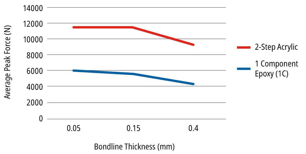
An evaluation of the same behaviour with a tensile lap shear test, according to ASTM D1002-01, yielded the values summarised in Table 19.

| Bond Line Thickness mm (in) | 0.05 (0.002 in) | 0.15 (0.006 in) | 0.4 (0.016 in) | |
| 2-step acrylic adhesive | Peak force (N) | 5,396 | 6,033 | 3,499 |
| 6,104 | 5,326 | 4,350 | ||
| 6,036 | 5,336 | 3,993 | ||
| 5,649 | 5,761 | 4,550 | ||
| 6,579 | 5,696 | 5,353 | ||
| Average peak force (N) | 5,953 | 5,630 | 4,349 | |
| Standard deviation (N) | 454 | 301 | 688 | |
| 1C heat curing epoxy | Peak force (N) | 12,434 | 10,248 | 9,359 |
| 12,019 | 11,677 | 10,024 | ||
| 10,579 | 11,776 | 9,026 | ||
| 11,275 | 12,537 | 9,276 | ||
| 10,986 | 11,328 | 9,160 | ||
| Average peak force (N) | 11,459 | 11,513 | 9,369 | |
| Standard deviation (N) | 758 | 833 | 387 | |

The results obtained in Tables 18 and 19 show how the strength of rigid adhesives varies with the thickness of the adhesive applied. In Table 18, the torque clearly decreases with increasing thickness for a two-step no-mix acrylic, while it has a less significant impact on the torque strength for a 1C heat curing epoxy. Table 19 shows how the performance of both products decreases as the adhesive thickness increases.
These data show how important it is to apply the correct thickness of adhesive to achieve the maximum desired performance.

